English
 English
 français
 Deutsch
 русский
 español
 português
 Nederlands
 العربية
 Polski
 中文
中文
Oct 08, 2026
Read More

latest News
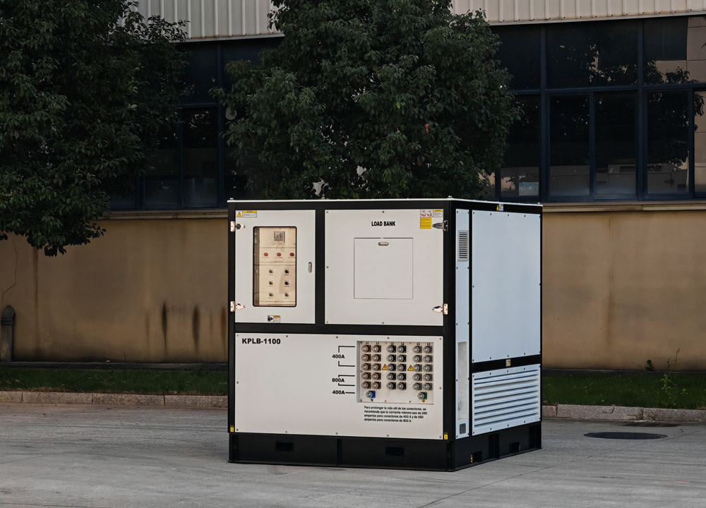
In the field of power and power equipment testing, we often hear about the "artificial load bank." Many people wonder: why is a device that consumes electricity called an "artificial load"? What is the difference between it and the "real loads" we use daily, such as lamps, motors, and appliances? In fact, the core of an artificial load is not "useless power consumption," but precise simulation. Real electrical equipment operates under complex and variable conditions. An artificial load bank, using the three basic electrical components—resistor (R), inductor (L), and capacitor (C)—replicates the electrical characteristics of various loads, providing a "full-operating-condition checkup" for generator sets, UPS systems, transformers, switchgear, and more. The three RLC artificial loads each have their own roles, complementing each other to cover the vast majority of load scenarios in power systems. In this article, we will break down in plain language the working logic, characteristic differences, and practical applications of these three core artificial loads, so you can understand the fundamental logic behind power testing. I. The Foundation: Pure Resistive Load – The "Stable Power Consumer" of Power Systems The resistive load is the most basic and commonly used load type in a load bank, and it is the closest to the general public's understanding of power consumption, corresponding to purely resistive devices in daily life such as electric water heaters, incandescent lamps, and electric heating elements. Its working principle is simple and straightforward, following Joule's law: when current passes through specially designed power resistor elements, electrical energy is 100% converted into heat, which is then dissipated into the air through cooling systems such as fans and heat-dissipating grilles, thereby steadily consuming the active power output from the power source under test. The entire process generates no magnetic field, stores no electrical energy, and simply consumes power. In terms of electrical characteristics, the voltage and current of a resistive load are perfectly in phase, with no phase difference. The power factor is always 1, and the operating state is extremely stable. Engineers can precisely control the power consumption by adjusting the number of resistor stages connected in parallel, simulating steady-state operating conditions of the power supply. In actual testing, resistive loads mainly address basic power supply stability verification. For example, they are used to test voltage and frequency stability of generator sets under no-load, full-load, and overload conditions, to check the continuous power supply capability of UPS systems, and to remove carbon deposits in generators that have been running lightly loaded for extended periods. Any test that requires measuring the rated active power and steady-state load-carrying capacity of a power source depends on resistive loads. &...
Read More
In the vast and harsh marine environment, offshore drilling platforms stand as man-made "islands" that explore and exploit precious oil and gas resources beneath the seabed. Behind every successful drilling operation, there is an unsung hero providing stable and reliable power—the diesel generator set. As the core power source of offshore drilling platforms, it undertakes the important mission of supplying electricity for all equipment and systems, ensuring the safety, efficiency and continuity of offshore operations. This article will popularize the key knowledge of diesel generator sets for offshore drilling platforms, helping you understand their working principles, special requirements, application scenarios and maintenance essentials. 1. What is an Offshore Drilling Diesel Generator Set? An offshore drilling diesel generator set is a special power generation equipment designed and manufactured for the unique environment of offshore drilling platforms. It is mainly composed of four core components: diesel engine, generator, control system and auxiliary equipment (cooling system, fuel system, lubrication system, etc.). Different from land-based diesel generator sets, offshore models must undergo special design and transformation to adapt to the harsh marine conditions such as high salt spray, high humidity, strong vibration, limited space and frequent extreme weather. Its core function is to convert the chemical energy of diesel into mechanical energy through the diesel engine, and then convert the mechanical energy into electrical energy through the generator, so as to provide stable AC or DC power for the entire drilling platform. From the huge drilling rigs, mud pumps and well control equipment to the daily life facilities such as lighting, air conditioning and communication systems on the platform, almost all electrical equipment depends on the power supply of diesel generator sets. 2. Working Principle: How Does It Generate Power Continuously? The power generation process of offshore diesel generator sets follows a simple and efficient energy conversion chain: diesel combustion → mechanical energy output → electrical energy generation, which is mainly completed through the coordinated operation of the diesel engine and the generator. First, the diesel engine completes a four-stroke working cycle to generate mechanical energy. The four strokes include intake stroke, compression stroke, power stroke and exhaust stroke. During the intake stroke, air is sucked into the cylinder; in the compression stroke, the piston compresses the air to increase its temperature and pressure; when the compression stroke is nearly completed, the fuel injector sprays atomized diesel into the high-temperature and high-pressure air, which ignites and burns quickly, generating high-temperature and high-pressure gas to push the piston down to do work (power stroke); finally, the exhaust valve opens, and the piston pushes the exhaust gas out of the c...
Read More
In high-altitude regions (typically defined as areas above 1,000 meters above sea level), the unique environmental conditions—such as thin air, low oxygen content, large temperature differences, strong ultraviolet radiation, and frequent geological activities—pose significant challenges to the stable operation of diesel generator sets. Unlike low-altitude environments, diesel generators here face issues like power loss, increased fuel consumption, and startup difficulties if not properly selected or maintained. This article aims to popularize the core knowledge of using diesel generator sets in high-altitude areas, helping users avoid common pitfalls and ensure reliable power supply. 1. How High-Altitude Environments Affect Diesel Generator Sets The primary impact of high altitudes on diesel generators stems from the thin air, which directly disrupts the engine’s combustion process and the overall performance of the unit. Here are the key effects and their underlying causes: 1.1 Significant Power Output Reduction Diesel engines rely on sufficient oxygen to burn fuel efficiently. At high altitudes, atmospheric pressure decreases, leading to lower air density and reduced oxygen content—for every 1,000-meter increase in altitude, oxygen levels drop by approximately 10%. This insufficient oxygen supply results in incomplete combustion, directly reducing the engine’s power output. The extent of power loss varies by engine type: • Naturally aspirated engines: Power decreases by 10%–12% per 1,000 meters, and even up to 15% for some models in extreme cases. • Turbocharged engines: Forced induction helps compensate for oxygen deficiency, but power still drops by 3%–8% per 1,000 meters. For example, a 500kW generator in Denver (5,280 feet, approximately 1,609 meters) will only deliver 408kW, a loss of 18%. At an altitude of 4,000 meters, the actual output power of a diesel generator may be only 60% of its sea-level rating, and at 5,000 meters, a 60kW generator may only provide around 36kW of power. 1.2 Increased Fuel Consumption and Poor Combustion Incomplete combustion due to oxygen shortage means the generator needs more fuel to maintain the same power output. At 3,000 meters above sea level, fuel consumption rates can increase by 8%–12% compared to low-altitude areas. Additionally, unburnt fuel leads to carbon buildup in the engine, accelerating wear of components like pistons and cylinders, and increasing maintenance costs over time. 1.3 Reduced Cooling Efficiency and Overheating Risks Air density at high altitudes is much lower than at sea level, which significantly impairs the heat dissipation capacity of the generator’s cooling system—especially for air-cooled units. For every 1,000-meter increase in altitude, the temperature rise of the unit increases by approximately 0.5–1℃. Poor heat dissipation can cause the engine and generator to overheat, leading to reduced ...
Read More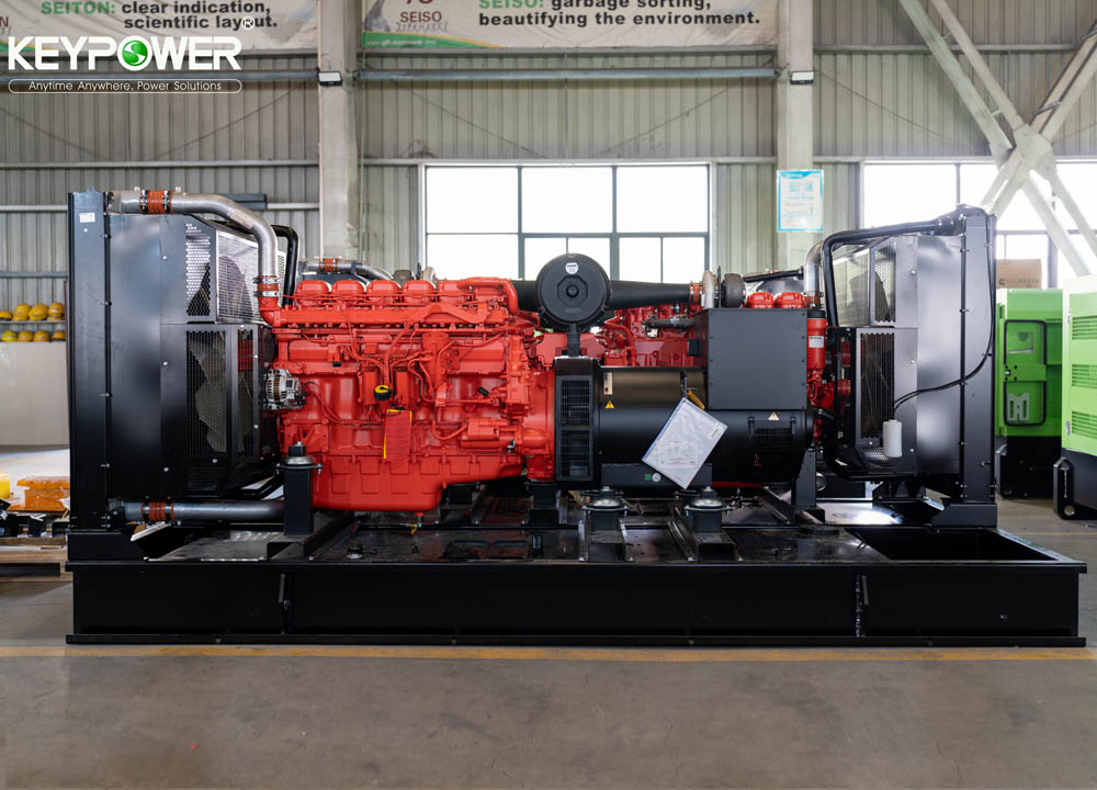
Mining is a cornerstone of the global economy, powering industries from construction to manufacturing with essential raw materials. Yet, the harsh and remote environments of mining sites—often far from stable grid power—pose a critical challenge: ensuring a reliable, continuous power supply to keep operations running safely and efficiently. This is where mining diesel generator sets step in, serving as the unsung heroes that provide the lifeblood of mining activities, whether in open-pit quarries or deep underground mines. In this article, we will demystify these vital pieces of equipment, exploring their working principles, key applications, unique features, and future trends. What Are Mining Diesel Generator Sets? A mining diesel generator set is a specialized power generation device that combines a diesel engine with an alternator (generator head) to convert the chemical energy of diesel fuel into electrical energy. Unlike ordinary diesel generators, those designed for mining are engineered to withstand the most demanding conditions—extreme temperatures, high altitude, heavy dust, vibration, and humidity. They are built for durability, reliability, and high performance, as any power outage in a mining site can lead to costly downtime, equipment damage, or even safety hazards such as gas accumulation or tunnel flooding. A complete mining diesel generator set consists of five core components, each playing a crucial role in its operation: the diesel engine (the power source), the alternator (which converts mechanical energy to electrical energy), the fuel system (including tanks, filters, and injectors), the cooling and exhaust systems (to prevent overheating and reduce emissions), and the control panel (to monitor, regulate, and protect the unit). How Do Mining Diesel Generator Sets Work? The working principle of a mining diesel generator set is a straightforward yet precise process that converts fuel into usable electricity, with built-in safeguards to ensure stability and safety: 1.Air Intake and Compression: The diesel engine draws in air, which is then compressed to a high pressure and temperature (typically 500–700°C) due to the engine’s high compression ratio (14:1 to 25:1). 2.Fuel Injection and Combustion: A high-pressure fuel pump sprays atomized diesel into the compressed hot air. Unlike gasoline engines, diesel engines do not use spark plugs—instead, the diesel ignites spontaneously when it comes into contact with the hot compressed air. 3.Power Generation: The combustion of diesel creates high-pressure gas that pushes the engine’s pistons, converting linear motion into rotational motion of the crankshaft. The crankshaft then drives the alternator’s rotor to spin at high speed, creating a rotating magnetic field. The stator windings cut through this magnetic field, generating three-phase alternating current (AC) electricity. 4.Control and Protection: The control panel co...
Read More
When shopping for motors—whether for household appliances, industrial equipment, or power tools—one of the most critical decisions is choosing between a copper wire motor and an aluminum wire motor. While both serve the same core purpose of converting electrical energy into mechanical energy, their materials drastically impact performance, efficiency, lifespan, and cost. In this guide, we break down the key differences between copper and aluminum wire motors, help you identify them easily, and advise which one is right for your needs. What’s the Core Difference? Material Matters The primary distinction between these two motor types lies in the material used for their windings—the coiled wires inside the motor that create the magnetic field. Copper and aluminum have different electrical, thermal, and mechanical properties, which translate to noticeable differences in how the motors perform in real-world use. Key Differences Between Copper Wire Motors and Aluminum Wire Motors 1. Electrical Conductivity & Energy Efficiency Electrical conductivity is the most important factor affecting a motor’s efficiency. Copper is an excellent conductor of electricity—far better than aluminum. Here’s how this plays out: • Copper Wire Motors: Low electrical resistance means less energy is lost as heat during operation. This results in higher energy efficiency (often 5-10% more efficient than aluminum motors), lower electricity bills, and less wasted energy. They also maintain consistent performance even under heavy loads. • Aluminum Wire Motors: Higher electrical resistance causes more energy to be converted into heat. This leads to lower efficiency, higher power consumption, and faster overheating—especially when used for extended periods or heavy-duty tasks. For example, a 1HP copper wire motor will use less electricity than an aluminum wire motor of the same power rating, making it a better choice for long-term use. 2. Heat Resistance & Durability Motors generate heat during operation, and the ability to withstand high temperatures directly impacts their lifespan and reliability. • Copper Wire Motors: Copper has a higher melting point (1085°C) and better thermal conductivity than aluminum (660°C). It resists oxidation and corrosion, even at high temperatures, which prevents wire breakage and motor failure. Copper windings also handle frequent start-stop cycles better, making them more durable and longer-lasting (typically 10-15 years with proper maintenance). • Aluminum Wire Motors: Aluminum oxidizes easily when heated, forming a layer of aluminum oxide that increases resistance and can cause overheating. The metal is also more brittle than copper, so it’s prone to breaking during installation or vibration. Aluminum motors have a shorter lifespan (usually 5-8 years) and higher failure rates, especially in harsh or high-temperature environm...
Read More
When using a diesel generator, whether for emergency backup power, construction sites, or remote areas without grid access, proper grounding is non-negotiable for safety. Grounding (also called earthing) creates a safe path for electrical current to flow into the earth in the event of a fault, preventing electric shocks, equipment damage, and even fires. Many users overlook this critical step, putting themselves, their workers, and their property at risk. This guide will break down why grounding is essential, how to do it correctly, and key precautions to keep in mind. Why Is Grounding a Diesel Generator Necessary? Diesel generators produce electrical power by converting mechanical energy into electrical energy. During operation, faults can occur—such as a damaged power cord, a short circuit in the generator’s internal wiring, or a malfunctioning component—that cause "live" electrical parts to come into contact with the generator’s metal frame or external surfaces. Without a proper ground, anyone who touches these energized surfaces could receive a life-threatening electric shock. Additionally, grounding helps stabilize the generator’s electrical system, reducing the risk of voltage surges that can damage sensitive equipment connected to the generator (such as computers, medical devices, or industrial machinery). It also protects the generator itself from internal damage caused by fault currents, extending its lifespan and ensuring reliable operation when you need it most. Key Terms You Need to Know Before diving into the grounding process, it’s important to understand a few basic terms to avoid confusion: • Ground Electrode: A metal rod, plate, or other conductor buried in the earth that provides a direct connection to the ground. Common types include copper-clad steel rods, galvanized steel rods, and ground plates. • Ground Wire/Cable: A thick, insulated copper wire that connects the generator’s grounding terminal to the ground electrode. It must be rated for the generator’s maximum current to handle fault currents safely. • Grounding Terminal: A dedicated metal terminal on the generator (usually marked with a "ground" symbol ⚡ or the word "GROUND") where the ground wire is attached. • Neutral-Ground Bond: In some generators, the neutral wire (white wire) is bonded to the ground at the generator. This is typically required for single-phase generators and ensures proper fault current pathing. Step-by-Step Guide to Safely Grounding a Diesel Generator Follow these steps carefully to ensure your diesel generator is grounded correctly. Note: If you are not familiar with electrical work, it is always best to hire a licensed electrician to perform this task. Step 1: Choose the Right Ground Electrode The ground electrode is the foundation of a safe grounding system. For most diesel generator applications, a copper-clad steel ground rod (8 to 10 feet long, ½ t...
Read More
Generators are vital backup systems, but how do you know they’ll work when needed? Load bank testing provides the answer. Why Test Generators with Load Banks? 1. Capacity Verification: Confirm the generator can deliver its rated power. 2. Heat and Efficiency Analysis: Evaluate performance under thermal stress. 3. Response Testing: Measure startup times and load fluctuations handling. Step-by-Step Testing Process 1. Preparation: Connect load bank to generator output, set safety protocols. 2. Load Incrementation: Gradually increase load (25% → 50% → 75% → 100%). 3. Data Collection: Monitor voltage stability, fuel consumption, temperature. 4. Overload Test: Briefly apply 110% load to assess emergency resilience. 5. Report Analysis: Identify weaknesses (e.g., voltage drop > 3% is alarming). Common Issues Detected Engine overheating under load. Voltage sag due to poor AVR tuning. Excessive fuel consumption indicating inefficiency. Best Practices Schedule tests quarterly or as per industry standards. Use certified load banks with real-time monitoring. Perform tests in ambient conditions matching real-world scenarios. Real-world Example Hospitals rely on load bank tests to ensure generators can power life-saving equipment during grid outages, avoiding medical emergencies. Conclusion Load bank testing is a preventive investment—protecting lives and businesses by ensuring generators perform flawlessly when crises strike.
Read More


 IPv6 network supported