
Resistor, Inductor, Capacitor? How Do the Three Major "Artificial Loads" in a Load Bank Work?
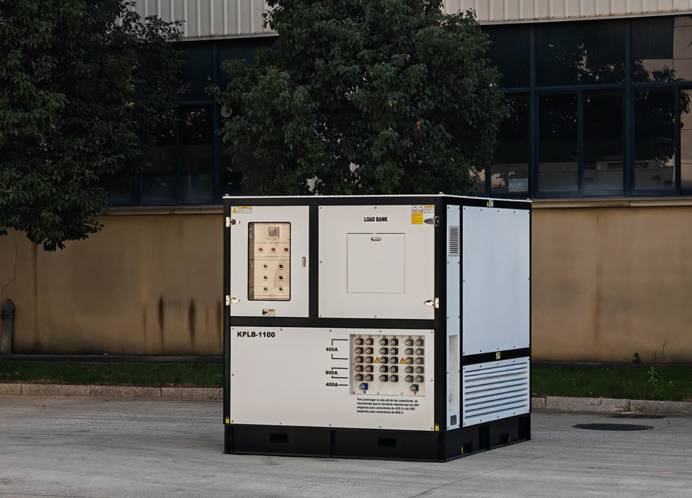
In the field of power and power equipment testing, we often hear about the "artificial load bank." Many people wonder: why is a device that consumes electricity called an "artificial load"? What is the difference between it and the "real loads" we use daily, such as lamps, motors, and appliances?
In fact, the core of an artificial load is not "useless power consumption," but precise simulation. Real electrical equipment operates under complex and variable conditions. An artificial load bank, using the three basic electrical components—resistor (R), inductor (L), and capacitor (C)—replicates the electrical characteristics of various loads, providing a "full-operating-condition checkup" for generator sets, UPS systems, transformers, switchgear, and more.
The three RLC artificial loads each have their own roles, complementing each other to cover the vast majority of load scenarios in power systems. In this article, we will break down in plain language the working logic, characteristic differences, and practical applications of these three core artificial loads, so you can understand the fundamental logic behind power testing.
I. The Foundation: Pure Resistive Load – The "Stable Power Consumer" of Power Systems
The resistive load is the most basic and commonly used load type in a load bank, and it is the closest to the general public's understanding of power consumption, corresponding to purely resistive devices in daily life such as electric water heaters, incandescent lamps, and electric heating elements.
Its working principle is simple and straightforward, following Joule's law: when current passes through specially designed power resistor elements, electrical energy is 100% converted into heat, which is then dissipated into the air through cooling systems such as fans and heat-dissipating grilles, thereby steadily consuming the active power output from the power source under test. The entire process generates no magnetic field, stores no electrical energy, and simply consumes power.
In terms of electrical characteristics, the voltage and current of a resistive load are perfectly in phase, with no phase difference. The power factor is always 1, and the operating state is extremely stable. Engineers can precisely control the power consumption by adjusting the number of resistor stages connected in parallel, simulating steady-state operating conditions of the power supply.
In actual testing, resistive loads mainly address basic power supply stability verification. For example, they are used to test voltage and frequency stability of generator sets under no-load, full-load, and overload conditions, to check the continuous power supply capability of UPS systems, and to remove carbon deposits in generators that have been running lightly loaded for extended periods. Any test that requires measuring the rated active power and steady-state load-carrying capacity of a power source depends on resistive loads.
II. The Dynamic Player: Pure Inductive Load – Simulating the "Magnetic-Field Energy Consumption" of Industrial Equipment
Most industrial equipment in our daily lives is not purely resistive. Pumps, fans, compressors, motors, and other devices with coils exhibit inductive load characteristics during operation. The inductive artificial load is specifically designed to replicate such industrial loads.
The core component of an inductive load is an insulated copper coil, and its working logic is completely different from that of a resistive load. Instead of directly converting electrical energy into heat, it uses the principle of electromagnetic induction – after energization, it establishes an alternating magnetic field around the coil, and the continuous maintenance of this magnetic field consumes electrical energy. This type of consumption is reactive power, which does not perform real work, but is nevertheless an indispensable form of load in power systems.
The most prominent electrical characteristic of an inductive load is that current lags behind voltage, generating lagging reactive power and lowering the overall power factor of the circuit. Simply put, the voltage reaches its peak first, and the current lags behind for a while before catching up – a common characteristic of industrial power grids.
Its testing value mainly lies in simulating industrial operating conditions. While ordinary resistive loads can only test ideal steady-state conditions, inductive loads can simulate the inductive impact of motor starting and large equipment operation, test the adaptability of power supplies to lagging power and low power factor conditions, and verify the operational stability of generators and power grids under complex industrial loads – helping to avoid voltage fluctuations and low power supply efficiency after actual deployment.
III. The Compensator: Pure Capacitive Load – The "Phase Adjuster" of Power Systems
The capacitive load is the most unique among the three. Everyday electrical equipment rarely exhibits purely capacitive characteristics. Its primary role is not simply to simulate loads, but to compensate for phase deviations in the power grid and balance power conditions – it is the "calibration tool" of power testing.
The core principle of a capacitive load is charge storage and alternating release. The capacitor itself does not consume active power. After energization, it quickly stores charge; during the alternating positive and negative half-cycles of AC, it releases the charge and feeds current back into the circuit, completing a periodic charge-discharge cycle. The entire process involves almost no energy loss, producing only capacitive reactive power.
In terms of electrical characteristics, the capacitive load is the exact opposite of the inductive load, exhibiting current leading voltage. It effectively cancels out the current lag caused by inductive loads, raises the circuit power factor, and balances phase differences in the grid.
In actual testing, capacitive loads are mainly used for grid optimization tests and non-standard operating condition checks. On one hand, they can simulate capacitive load scenarios to test the phase adaptation capability of precision power supplies and voltage regulators. On the other hand, they can be combined with inductive loads for power factor compensation tests, calibrating the reactive power regulation accuracy of generator sets and switchgear. This addresses common issues in industrial grids such as low power factor and high power losses, ensuring efficient power system operation.
IV. Combined RLC Loads: Reproducing Real-World Complex Power Scenarios
From the principles of the three individual load types, it is clear that each has its limitations, and no single type can fully represent real-world power consumption. In practice, loads in factories, buildings, and data centers are mixtures of resistive, inductive, and capacitive elements. This is why high-end load banks adopt combined RLC designs.
The resistor consumes active power, simulating the base electrical load. The inductor simulates mainstream inductive loads such as industrial motors, replicating lagging characteristics. The capacitor provides phase compensation to correct grid deviations. By adjusting the ratios of the three elements as needed and working together, they can accurately simulate power factors across the entire 0–1 range, perfectly reproducing complex power environments in residential, industrial, data center, and other applications.
Such combined artificial load banks are also essential equipment for factory acceptance testing of generator sets, complete UPS system validation, grid modification debugging, and annual inspections of backup power supplies. They enable comprehensive checks of key parameters such as load-carrying capacity, voltage regulation accuracy, impact resistance, and reactive power adaptability, helping to preemptively identify potential faults before actual operation.



 IPv6 network supported
 English
 English
 français
 Deutsch
 русский
 español
 português
 Nederlands
 العربية
 Polski
 中文
中文